Relationship
How entities act upon each other or are associated with each other. Think of relationships as verbs. For example, the named student might register for a course. The two entities would be the student and the course, and the relationship depicted is the act of enrolling, connecting the two entities in that way.
Relationships are typically shown as diamonds or labels directly on the connecting lines.
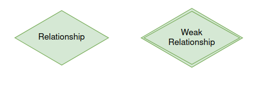
Degree of a relationship set
The number of different entity sets participating in a relationship set is called as degree of a relationship set.
Unary Relationship
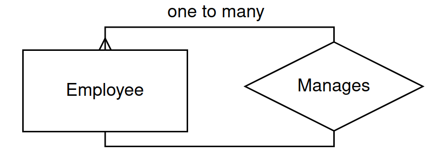
A unary relationship (also known as a recursive relationship) is a relationship where an entity in a table is related to another entity in the same table. This occurs when entities of the same type are associated with each other.
1. Employee-Manager Relationship
Scenario: In a company, each employee can have a manager, who is also an employee.
Entity:
EmployeeRelationship: “Manages” (an employee is managed by another employee)
Table Structure:
CREATE TABLE Employee (
    EmployeeID SERIAL PRIMARY KEY,
    Name TEXT NOT NULL,
    ManagerID INT REFERENCES Employee(EmployeeID)
);
Explanation:
EmployeeIDis the primary key for employees.ManagerIDrefers to anotherEmployeeIDin the same table, creating a recursive relationship.Example Data:
EmployeeID
Name
ManagerID
1
Alice
NULL
2
Bob
1
3
Charlie
1
Alice is a manager (no
ManagerIDbecause she’s at the top level).Bob and Charlie report to Alice.
Person-Family Relationship
Scenario: In a family tree, a person can have a parent, who is also a person.
Entity:
PersonRelationship: “Is Parent Of” (a person can have a parent or be a parent)
Table Structure:
CREATE TABLE Person (
    PersonID SERIAL PRIMARY KEY,
    Name TEXT NOT NULL,
    ParentID INT REFERENCES Person(PersonID)
);
Explanation:
PersonIDuniquely identifies each person.ParentIDreferences thePersonIDof the person’s parent.Example Data:
PersonID
Name
ParentID
1
John
NULL
2
Alice
1
3
Bob
1
John is the parent of Alice and Bob.
Unary relationships are useful for modeling hierarchical or self-referencing relationships. The foreign key within the same table is used to enforce this relationship.
Binary Relationship
A binary relationship occurs between two different entities in a database. It defines the association between instances of two separate entity types. There are three main types of binary relationships based on cardinality: one-to-one (1:1), one-to-many (1:N), and many-to-many (M:N).
One-to-One (1:1) Relationship
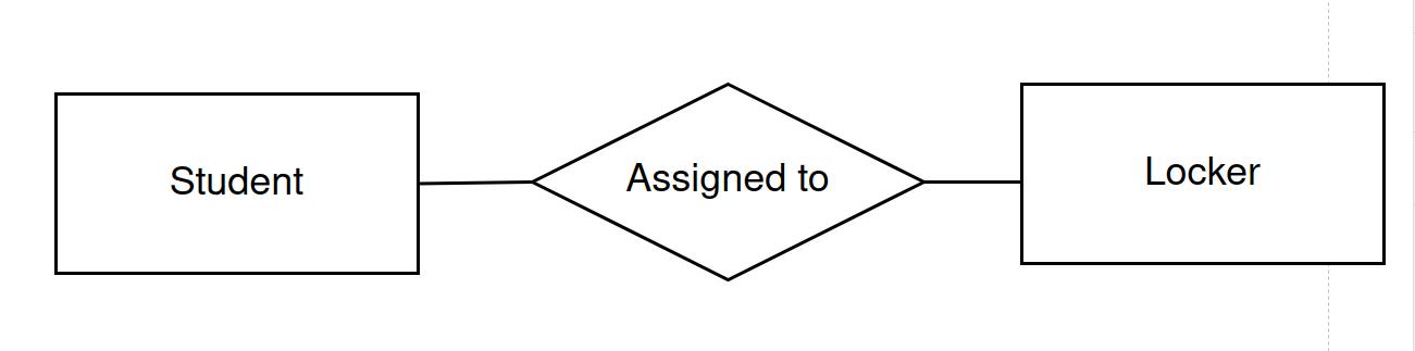
Scenario: A university maintains a database of students and their assigned lockers. Each student is assigned exactly one locker, and each locker is assigned to exactly one student.
Entities:
StudentLocker
Relationship: “Assigned to”
Table Structure
CREATE TABLE Student (
    StudentID SERIAL PRIMARY KEY,
    Name TEXT NOT NULL
);

CREATE TABLE Locker (
    LockerID SERIAL PRIMARY KEY,
    LockerNumber TEXT NOT NULL UNIQUE,
    StudentID INT UNIQUE REFERENCES Student(StudentID)
);
Explanation:
The
StudentIDinLockeris a foreign key referencingStudentIDinStudent.StudentIDinLockeris unique, ensuring one locker per student.Example Data:
StudentID
Name
1
Alice
2
Bob
LockerID
LockerNumber
StudentID
1
L001
1
2
L002
2
One-to-Many (1:N) Relationship
Scenario: A department in a company has multiple employees. Each employee belongs to one department.
Entities:
DepartmentEmployee
Relationship: “Belongs to”
Table Structure
CREATE TABLE Department (
    DepartmentID SERIAL PRIMARY KEY,
    DepartmentName TEXT NOT NULL
);

CREATE TABLE Employee (
    EmployeeID SERIAL PRIMARY KEY,
    Name TEXT NOT NULL,
    DepartmentID INT REFERENCES Department(DepartmentID)
);
Explanation:
The
DepartmentIDinEmployeeis a foreign key referencingDepartmentIDinDepartment.Multiple employees can belong to the same department, but each employee belongs to only one department.
Example Data:
DepartmentID
DepartmentName
1
HR
2
IT
EmployeeID
Name
DepartmentID
1
Alice
1
2
Bob
2
3
Charlie
1

Many-to-Many (M:N) Relationship
Scenario: Students can enroll in multiple courses, and each course can have multiple students.
Entities:
StudentCourse
Relationship: “Enrolled in”
Table Structure
CREATE TABLE Student (
    StudentID SERIAL PRIMARY KEY,
    Name TEXT NOT NULL
);

CREATE TABLE Course (
    CourseID SERIAL PRIMARY KEY,
    CourseName TEXT NOT NULL
);

CREATE TABLE Enrollment (
    StudentID INT REFERENCES Student(StudentID),
    CourseID INT REFERENCES Course(CourseID),
    PRIMARY KEY (StudentID, CourseID)
);
Explanation:
The
Enrollmenttable acts as a bridge betweenStudentandCourse.Each row in
Enrollmentrepresents a unique combination of a student and a course.Example Data:
StudentID
Name
1
Alice
2
Bob
CourseID
CourseName
1
Mathematics
2
Computer Science
StudentID
CourseID
1
1
1
2
2
1
